B6U 2-WIRE UNIVERSAL TEMPERATURE TRANSMITTER (HART communication, intrinsically safe)
Functions & Features • Universal input: mV, V, T/C, RTD, resistance and potentiometer • High accuracy • HART communication • Intrinsically safe approval • Programming via hand-held communicator or via PC • A wide variety of T/C and RTD types • User’s temperature table can be used • Self diagnostics • Input-output isolated
MODEL: B6U–[1][2]
ORDERING INFORMATION • Code number: B6U-[1][2] Specify a code from below for each of [1] and [2]. (e.g. B6U-21). Use Ordering Information Sheet (No. ESU-7451). Factory standard setting will be used if not otherwise specified. Specify the country in which the product is to be used with the Safety Approval code 2.
[1] SAFETY APPROVAL 0: None 1: FM intrinsically safe 2: IECEx/ATEX intrinsic safety 5: FM nonincendive 7: TIIS intrinsic safety (CE not available)
[2] LCD DISPLAY 0: Without 1: With
RELATED PRODUCTS • Outdoor enclosure (model: 6BX-E) • USB interface Bell202 modem (model: COP-HU) Usable in ‘non-hazardous’ area only. • Hand-held communicator • AMS (version 6.0 or higher) • PC configurator software (model: B6UCFG) Downloadable at M-System’s web site.
GENERAL SPECIFICATIONS Electrical connection: M3.5 screw terminals (torque 0.8 N·m) Materials Transmitter housing: Flame-resistant resin (black) Screw terminals: Nickel-plated brass Isolation: Input to output Burnout (T/C, RTD, Potentiometer & Resistance): Upscale, downscale or no burnout selectable (standard: upscale); Also detects wire breakdown and overrange input exceeding the electrical design limit for DC input. Cold Junction Compensation (thermocouple input): CJC sensor incorporated User-configurable items: · Input sensor type · Number of wires (RTD & resistance) · Input range · Inverted output · Burnout · Damping time (via HART only, standard: 0) · Sensor calibration (via HART only) · Output calibration · Special linearization data (via HART only) · HART communication mode
HART COMMUNICATION Protocol: HART communication protocol HART address range: 0 – 15 (factory set to 0) Transmission speed: 1200 bps Digital current: Approx. 1 mAp-p when communicating Character format: 1 Start Bit, 8 Data Bits, 1 Odd Parity Bit, 1 Stop Bit Distance: 1.5 km (0.9 miles) HART communication mode: Master-Slave Mode and Burst Mode (factory set to Master-Slave) HART network mode: Point-to-Point Mode and Multi-drop Mode; automatically set to Multi-drop Mode when the address is set to other than 0.
LCD DISPLAY (option) Features: · Setting and display of input signals, engineering units and the transmitter operating status, etc. · Removable while the module is powered. Display size: 36 × 20 mm (1.42” × 0.79”) Characters Color: Black Format: • 2 rows of 5 alphanumeric characters: Top row: 7.4 mm high; Bottom row: 6.5 mm high, • Status indicators and engineering units For detail of the LCD panel indication, refer to the instruction manual. Display range: -99999 to 99999 Decimal point: In top row Read rate: 150 msec. Back light: None
INPUT SPECIFICATIONS The input type is factory-set to K thermocouple, and the input range to 0 to 100°C. See Table 1 for the available input type, the minimum span, and the maximum range. ■ DC mV & V Input resistance: ≥ 1 MΩ ■ Thermocouple Input resistance: ≥ 1 MΩ Burnout sensing: 130 nA ±10 % ■ RTD (2-wire, 3-wire or 4-wire) Input resistance: ≥ 1 MΩ Allowable leadwire resistance: Max. 20 Ω per wire ■ Resistance (2-wire, 3-wire or 4-wire) Excitation: 0.2 mA ±10 % Allowable leadwire resistance: Max. 20 Ω per wire ■ Potentiometer Excitation: 0.2 mA ±10% Allowable leadwire resistance: Max. 20 Ω per wire
OUTPUT SPECIFICATIONS Output range: 4 – 20 mA DC Operational range: 3.8 – 21.6 mA Load resistance vs. supply voltage: Load Resistance (Ω) = (Supply Voltage (V) – 12 (V)) ÷ 0.024 (A) (including leadwire resistance)
INSTALLATION Supply voltage · 12 – 42 V DC (non-approved) · 12 – 28 V DC (approved) Operating temperature: · Non-safety-approved unit: -40 to +85℃ (-40 to 185°F) · Safety-approved unit: See Safety Parameters for use in a hazardous location. · LCD display (full visibility): -30 to +80℃ (-22 to 185°F) Operating humidity: 0 to 95 %RH (non-condensing) Weight: 150 g (0.33 lb) including the LCD
PERFORMANCE Accuracy: See Table 1 and ‘Explanations of Terms.’ Cold junction compensation error: ±0.5℃ (±0.9°F) Temp. coefficient: ±0.015 %/°C (±0.008 %/°F) of max. span at -5 to +55°C [23 to 131°F] Start-up time: Approx. 8 sec. Response time: ≤ 2 sec. (0 – 90 %) with damping time set to 0 and when not communicating via HART. Supply voltage effect: ±0.003 % × [Output Span] / 1 V Insulation resistance: ≥ 100 MΩ with 500 V DC Dielectric strength: 1500 V AC @1 minute (input to output) Safety integrity level: Suitable for use in a safety instrumented system up to SIL1 or SIL2 if appropriate safety instructions are observed. Consult M-System.
EXPLANATIONS OF TERMS ■ ACCURACY This transmitter’s accuracy is theoretically defined as the addition of A/D and D/A conversion errors:
The A/D conversion error means that measured as HART signal which is A/D converted from the analog input signal. The D/A conversion error of this transmitter is relatively very small so that it does not really affect the unit’s overall performance. The “Accuracies” given in Table 1 therefore equals the A/D conversion error. The temperature drift (coefficient) or the cold junction compensation error is not included in the “Accuracy.” ■ CALCULATION EXAMPLES OF OVERALL ACCURACY IN % • DC Voltage 1) 0 – 200 mV Absolute value accuracy (Table 1): 40 μV 40 μV ÷ 200000 μV × 100 = 0.02 % < 0.1 % ➠ Overall accuracy = ±0.1% of span 2) 0 – 4 mV Absolute value accuracy (Table 1): 10 μV 10 μV ÷ 4000 μV × 100 = 0.25 % > 0.1% ➠ Overall accuracy = ±0.25 % of span • Thermocouple 1) K thermocouple, 0 – 1000°C Absolute value accuracy (Table 1): 0.25°C 0.1% × 1000°C = 1°C > 0.25°C CJC error (0.5°C) added: 1 + 0.5 = 1.5°C 1.5°C ÷ 1000°C × 100 = 0.15 % ➠ Overall accuracy including CJC error = ±0.15 % of span 2) K thermocouple, 50 – 150°C Absolute value accuracy (Table 1): 0.25°C 0.1 % × (150 – 50)°C = 0.1°C < 0.25°C CJC error (0.5°C) added: 0.25 + 0.5 = 0.75°C 0.75°C ÷ (150 – 50)°C × 100 = 0.75 % ➠ Overall accuracy including CJC error = ±0.75 % of span • RTD 1) Pt 100, -200 – 800°C Absolute value accuracy (Table 1): 0.15°C 0.15°C ÷ (800 – -200)°C × 100 = 0.015 % < 0.1 % ➠ Overall accuracy = ±0.1 % of span 2) Pt 100, 0 – 100°C Absolute value accuracy (Table 1): 0.15°C 0.15°C ÷ 100°C × 100 = 0.15 % > 0.1 % ➠ Overall accuracy = ±0.15 % of span
STANDARDS & APPROVALS Refer to the manuals to comply with the standards. EU conformity: ATEX Directive Ex ia EN 60079-11 EMC Directive EMI EN 61000-6-4 EMS EN 61000-6-2 RoHS Directive EN 50581 Safety approval: FM: Intrinsically safe Class I, Division 1, Groups A, B, C and D Class I, Zone 0, AEx ia IIC T4, T5 and T6 (Class 3600) (Class 3610) (ANSI/ISA 60079-0) (ANSI/ISA 60079-11) FM: Nonincendive Class I, Division 2, Groups A, B, C, and D Class I, Zone 2, Group IIC T4, T5 and T6 (Class 3600) (Class 3611) IECEx intrinsic safety Ex ia IIC T4, T5 and T6 Ga (IEC 60079-0) (IEC 60079-11) TIIS: Intrinsic safety Ex ia IIC T5 X
Mã số : 27HU 2-WIRE UNIVERSAL TEMPERATURE TRANSMITTER
DC mV, V & mA, T/C, RTD and resistance input
8-35 Vdc powered (max. 28 V approved)
ATEX Zone 0 approval
FM Class I, Div. 1 & Zone 0 approval
27HU 2-WIRE UNIVERSAL TEMPERATURE TRANSMITTER
M-System Việt Nam
Email: Sales@m-system.com.vn
Mã số : B6U 2-WIRE UNIVERSAL TEMPERATURE TRANSMITTER
DC mV, V & mA, T/C, RTD, Pot and resistance input
12-42 Vdc powered (max. 28 V approved)
ATEX Zone 0 approval
FM Class I, Div. 1 & 2 approval
B6U 2-WIRE UNIVERSAL TEMPERATURE TRANSMITTER
M-System Việt Nam
Email: Sales@m-system.com.vn
Mã số : 26TS1 THERMOCOUPLE TRANSMITTER
Specify K, E, J, T, B, R, S, N and temp. range. Special T/C acceptable
12-32 Vdc powered
Fast response 25 msec. optional
26TS1 THERMOCOUPLE TRANSMITTER
M-System Việt Nam
Email: Sales@m-system.com.vn
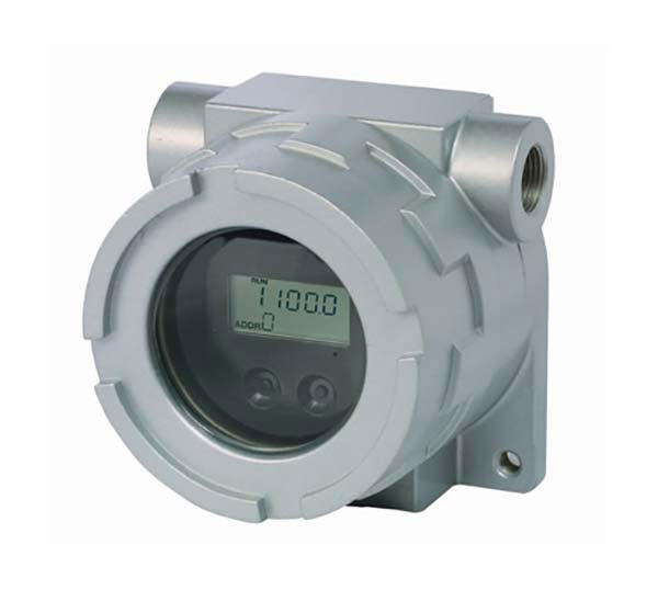
Mã số : B6U-B 2-WIRE UNIVERSAL TEMPERATURE TRANSMITTER
DC mV, V & mA, T/C, RTD, Pot and resistance input
12-42 Vdc powered (max. 28 V approved)
NEMA 4X, IP66/IP67 enclosure
ATEX Zone 0 approval
FM Class I, II, III, Div. 1 & Class I, II, Div. 2 approval
B6U-B 2-WIRE UNIVERSAL TEMPERATURE TRANSMITTER
M-System Việt Nam
Email: Sales@m-system.com.vn
Mã số : 27RS RTD TRANSMITTER
Pt100, Pt1000, Pt500 selectable
Function monitor LED optional
9-35 Vdc powered
ATEX Zone 0 approval
FM Class I, Div. 1 & Zone 0 approval
27RS RTD TRANSMITTER
M-System Việt Nam
Email: Sales@m-system.com.vn
Mã số : 27TS THERMOCOUPLE TRANSMITTER
K, E, J, T, B, R, S, C, D, N, U, L selectable
9-35 Vdc powered
ATEX Zone 0 approval
FM Class I, Div. 1 & Zone 0 approval
27TS THERMOCOUPLE TRANSMITTER
M-System Việt Nam
Email: Sales@m-system.com.vn
Mã số : 27U 2-WIRE UNIVERSAL TEMPERATURE TRANSMITTER
DC mV, V & mA, T/C, RTD and resistance input
9-35 Vdc powered
ATEX Zone 0 approval
FM Class I, Div. 1 & Zone 0 approval
27U 2-WIRE UNIVERSAL TEMPERATURE TRANSMITTER
M-System Việt Nam
Email: Sales@m-system.com.vn
Mã số : 27R RTD TRANSMITTER
Pt100, Pt1000, Pt500 selectable. Non-isolated.
Function monitor LED optional
9-35 Vdc powered
ATEX Zone 0 approval
FM Class I, Div. 1 & Zone 0 approval
27R RTD TRANSMITTER
M-System Việt Nam
Email: Sales@m-system.com.vn
Mã số : B5TS - THERMOCOUPLE TRANSMITTER
Specify K, E, J, T, B, R, S, N and temp. range. Special T/C acceptable
12-28 Vdc powered
Fast response 25 msec. optional
B5TS - THERMOCOUPLE TRANSMITTER
M-System Việt Nam
Email: Sales@m-system.com.vn
Mã số : 27HU-B 2-WIRE UNIVERSAL TEMPERATURE TRANSMITTER
DC mV, V & mA, T/C, RTD and resistance input
8-35 Vdc powered (max. 28 V approved)
ATEX Zone 0 approval
FM Class I, Div. 1 & Zone 0 approval
27HU-B 2-WIRE UNIVERSAL TEMPERATURE TRANSMITTER
M-System Việt Nam
Email: Sales@m-system.com.vn
Functions & Features
• Universal input: mV, V, T/C, RTD, resistance and
potentiometer
• High accuracy
• HART communication
• Intrinsically safe and explosion-proof approval
• Optional stainless steel enclosure
• Programming via hand-held communicator or via PC
• A wide variety of T/C and RTD types
• User’s temperature table can be used
• Self diagnostics
• Input-output isolated